Description
The YAV90PIN board is designed to cover the need to control the available power supplies in a test system to the device under test.
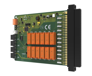
A VPC 90 series connector is used as interface with the fixture, guaranteeing more than 20.000 mating cycles. Two connector contacts per relay contact are used.
The board features three connectors in the back. The connector X01 is used to power the board and to connect to the CAN bus. X02 is to disconnect all the relays when its continuity is interrupted (ENABLE function). This function is managed by the emergency stop, and guarantees a rapid disconnection of all loads and power supply lines to the device under test when the emergency button pushed.
Each one of the terminals featured by the connector X03 are connected to the fixture through relays or directly from the power supply. This configuration provides the option to the designer to connect for instance loads or power supply lines needed inside the fixture direct or via a relay.
The module features a logic address setting by means of a set of dip switches. A maximum of 64x YAV90PIN boards are possible in one test system.
A virtual software panel, that can be used with National Instruments LabView® or TestStand®, is available to simply integrate the instrument into the test sequence.