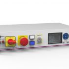
Power Management & MMI module

  • Platform safety management according to: EN 60947-5-1 and EN 60204.
  • PT100 temperature inputs with alarm function.
  • System cooling controlled by temperature input.
  • Precision AC voltage, current, phase & frequency measurement with alarm function.
  • Full Color LCD Graphic control display.
  • Run / down-time counters, non-erasable mem.
  • 8 floating bipolar switches for external control.
  • EPO; local and remote.
  • Direct connection and control over PDU.
  • 90dB alarm buzzer.
  • Connection for Can bus controlled light tower.
  • Ethernet port for network connection.
  • 2 configurable I/O’s.
  • switcable +24V pwr output.

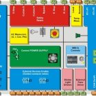
This module, named “6TL-MMI”, is designed to be the interface between an operator and a SYSTEM as well as being a metered power distribution unit (PDU) for it. The module is providing also safety controls, data bus interfaces, temperature control and timers.

The 6TL-MMI is suitable for any ATE, and specially for those based on CAN bus controlled devices, because in addition to the above functionalities, this module is also providing galvanic isolation up to 1500V for the CAN bus. This isolation will block potential disturbance towards the DUT.

The 6TL-MMI is powered from the grid through a bipolar switch for providing power to the Un-switched bus, and through an emergency stop with safety relays to provide power to the Switched bus.

The Switched bus is used to provide energy to the DUT as well as to all the power supplies that will be used to power up the DUT. The Un-switched bus (Two 10A Schuko plugs) is used for powering the control computer through a UPS.

The module includes a universal input DC power supply of 24VDC 8,3A with a thermal fan control. The 24VDC power outputs could be interrupted for energy saving while the system is in Stand-by mode or for resetting the modules.

The 6TL-MMI can be also used by the SYSTEM operator to choose options through the executive SW, or for starting/terminating the test execution.

Concerning the safety, note that a photoelectric barrier could be installed as part of the safety chain of the SYSTEM, as the 6TL-MMI provides power supply and automatic test and reset for it. Eight floating contacts (Potential free) are available for enabling external devices, that will also be part of the safety circuitry.

You must be registered to download the documentation.

Sign Up
All the data you have provided us shall be introduced into and treated in an automated data file belonging to S.A. Sistel, specially designed to meet the current relationship. Such data are confidential and belong solely to S.A. Sistel., who is the responsible for the file and is located at Solsonès, 87 . 08211 Castellar del Vallès, Barcelona. You are authorized to access, modify, cancel and deny the processing of the mentioned data by writing directly to the address specified above. In accordance with the right of access to information specified by the article 10 of the law currently in force 34/2002 dated 11 th. July related to the Services of the Information Society and Electronic Commerce, you are presently informed that the responsible for the web is S.A. Sistel., being available at the Internet domain www.6tlengineering.com with prior registering to the corresponding records, and to be contacted by users and/or interested parties at info@sasistel.es
Read our Privacy Policy
Log in

H73000700 Brochure
Login to download the file

730007E10
Login to download the file

MMI & PDU Technical Brochure (July 2013)
Login to download the file